|
|
|
|
|
|
|
|
|
|
|
|
|
|
|
|
|
|
|
|
|
|
|
|
|
|
|
|
|
|
 |
| |
>
INTRODUCTION
a
fascination with imagination |
| |
>
THEME PARK MAGIC
inspirational rides and attractions |
| |
>
A PHANTOM PLOT UNFOLDS
a 2003 test from Disneyland ideas |
| |
>
THE HAUNTING BEGINS
five
years of Halloween, 2004-2008 |
|
>
BACK FROM THE GRAVE
2010-2011 with new technology |
| |
>
A 2013 RESURRECTION
a mix of new and age-old effects |
| |
>
DAWN OF THE UNDEAD
2014
show, part one |
| |
>
THE ZOMBIES EMERGE
2014 show, part two |
| |
>
A CHANGING CONCEPT
2015 show, part one |
| |
>
BUILDING PNEUMATIC FIGURES
2015 show, part two |
| |
>
ROLL UP, ROLL UP!
2015
show, part three |
| |
>
INTO THE TUNNEL...
2016
show, part one |
| |
>
MAKING MONSTERS MOVE
2016
show, part two |
| |
>
TO HELL AND BACK
2016 show, part three |
| |
>
SHARPENING THE
SENSES
2017 show, part one |
| |
>
A MAGNETIC ATTRACTION
2017 show, part two |
| |
>
THE BIG EXECUTION
2017 show, part three |
|
|
|
| |
Improving movement with pneumatics |
|
|
|
|
|
|
|
|
|
|
|
|
|
|
|
|
|
|
|
|
|
|
|
|
|
|
|
|
|
|
| |
In the last two
displays, I had re-introduced movement in some of the
figures, however these all used electric motors with limited
torque. This meant that only parts of these figures, such as
heads and hands, could be moved easily. Using compressed air
instead would produce much bigger forces, allowing whole
top halves, or heavier sections of figures, to rock or move
about.
To create this movement, David introduced me to building
McKibben air muscles. These were invented in 1957 by Joseph
McKibben, originally to be used to help move artificial
limbs. One of David's projects was an impressive set of
animatronic legs, moved
using McKibben air muscles, to provide life-like human
movement.
The construction of these muscles involved wrapping a piece
of bicycle inner tube with electrical braiding, then
plugging both ends with pieces of dowel. One end had a hole
drilled through it where the air pipe was glued in. The
braiding was then fastened securely to the ends with jubilee
clips. Inflation of the tubing would cause the braiding to
widen and pull the ends of the muscle inwards. |
|
|
|
|
|
|
|
|
|
|
|
|
|
|
|
|
|
|
|
|
|
|
|
|
|
|
|
|
|
| |
 |
|
|
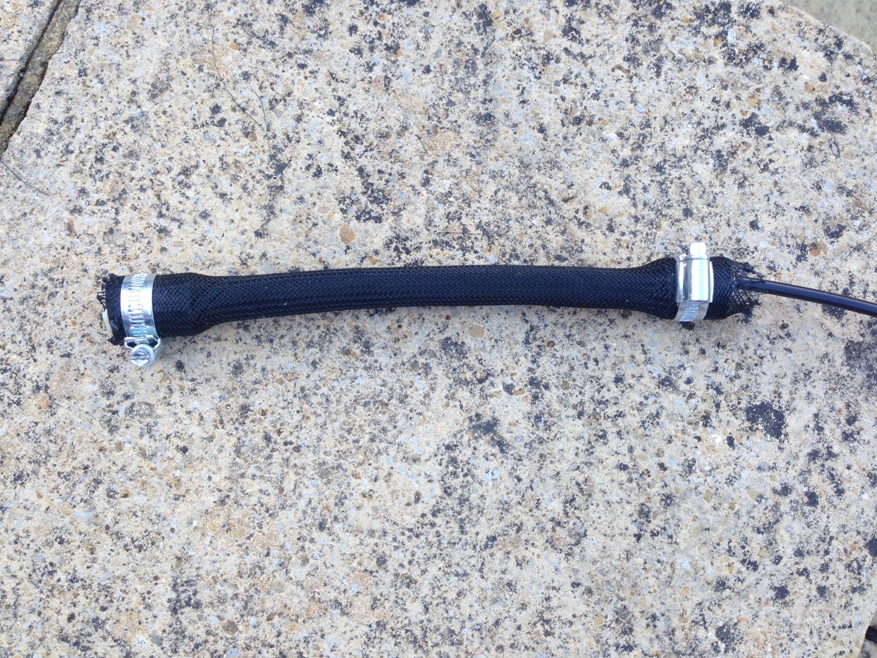
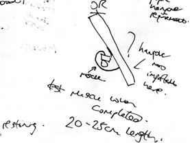
When compressed
air enters the muscle, it contracts lengthways. Then, when emptied of
air, it returns to its original length. By attaching these
to hinges and levers, movement can be produced.
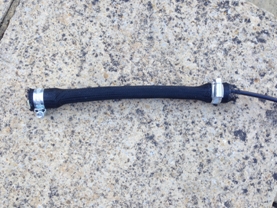
< Here is one of the first muscles I made. It had a length
of about 25cm, and a contraction of about 4cm when inflated.
To reduce air leakage, the two dowel bungs needed to be made
slightly conical, with the wider end towards the middle of
the muscle. This also helped to prevent them from being
pulled out when the muscle was in operation! |
|
|
|
|
|
|
|
|
|
|
|
|
|
|
|
|
|
|
|
|
|
|
|
|
|
|
|
|
|
|
|
|
|
|
|
|
|
|
|
|
|
| |
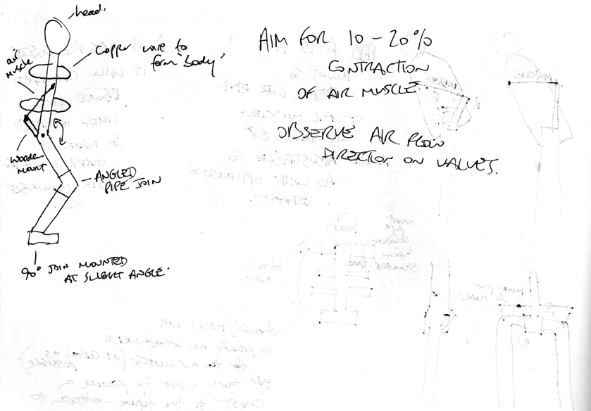
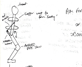
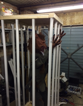
But how would
these muscles move the figures? One creature that I came up
with was the ‘wolfman’; an ill-fated hairy fellow who had
undergone some unfortunate transformation and ended up with
lupine features! I wanted him to
rock back and forth and rattle his cage as visitors
approached.
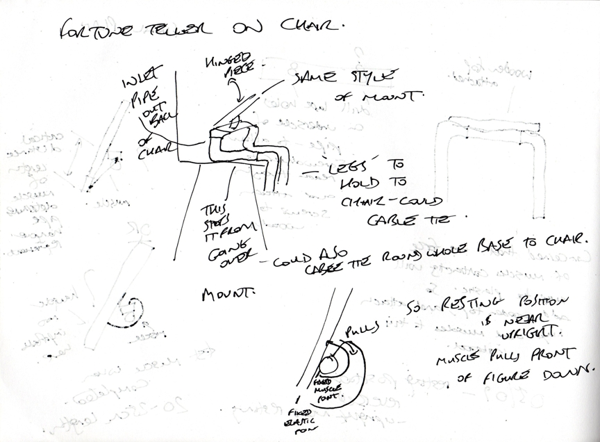
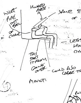
> This is one of my early drawings of the figure, showing
him with bent knees as if on hind legs, and a hinged torso.
I'd originally thought about mounting the air muscle at the
back, pulling the body upwards from behind... |
|
|
 |
|
|
|
|
|
|
|
|
|
|
|
|
|
|
|
|
|
|
|
|
|
|
|
|
|
|
|
|
|
| |
 |
|
|
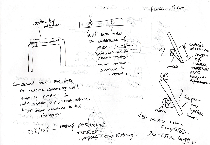
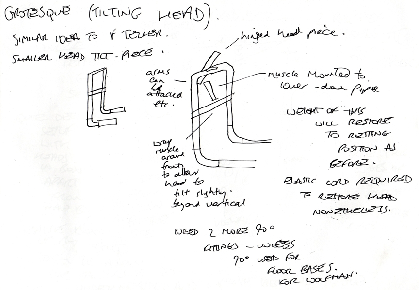
...but David
suggested that the muscle could be wrapped around a
cylinder, where it would unwind slightly on contraction. So
I made sure each figure had a
horizontal bar to which the hinged part attached; the muscle could
then be fitted to this part, and then wrapped around the bar
and secured.
Mounting it very close to the hinge was practical as I found
that it had immense pulling strength in operation. This
allowed for a greater distance of movement on the figure,
from the same small contraction of the muscle. |
|
| |
|
|
|
|
|
|
|
|
|
|
| |
|
|
|
|
|
|
|
|
|
|
|
|
|
|
|
|
|
|
|
|
|
|
|
|
|
|
|
|
|
|
|
|
|
|
| |
Making the muscles move |
|
|
|
|
|
|
|
|
|
|
|
|
|
|
|
|
|
|
|
|
|
|
|
|
|
|
|
|
|
|
|
|
|
|
|
|
|
| |
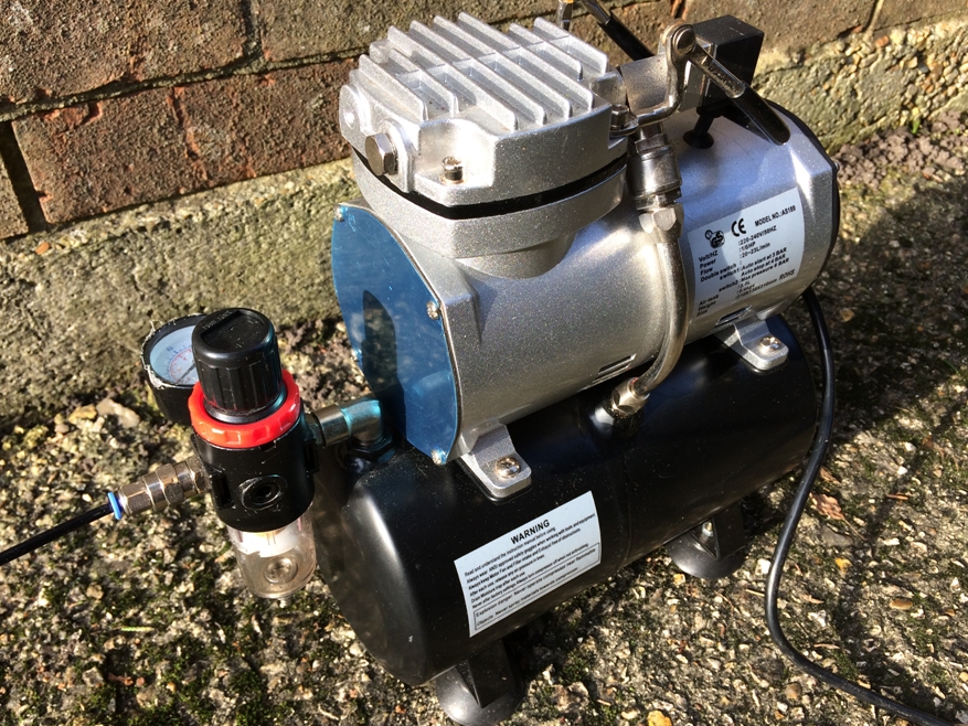
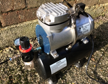
The pneumatic
system needed a compressor to supply air to the muscles.
I found an airbrush compressor online with a 3 litre tank.
The advantage of the air tank was that the compressor
could store air in reserve, allowing for muscles to be
repeatedly filled and emptied in longer bursts, or for
multiple muscles to be driven at the same time. I was
planning three moving figures, so this sounded like a good
idea! |
|
|
|
|
|
|
|
|
|
|
|
|
|
|
|
|
|
|
|
|
|
|
|
|
|
|
|
|
|
|
|
|
|
|
|
|
|
|
|
| |
The compressor
was capable of supplying air up to a pressure of 6 bar.
David informed me that the air muscles would work best at
around 1.5 to 3 bar, so this would be more than capable. It
also had a mode whereby it would charge the tank up to 4
bar pressure, then switch off. When the pressure dropped to
below 3 bar, it would switch on again and recharge.
This would prove to be very useful - it would have been
damaging to the compressor to leave it running permanently
(it would overheat), but if it was only to come on for short
periods to top up the tank, this would ensure a more or less
constant supply of air at the required pressure for the
figures all evening.
One other great benefit was that due to its relatively small
size and power, it was very quiet when running. It would
have been impractical to have had a massive compressor
rattling away at 90 or 100dB, despite the substantial
increase in air supply! Installed in a shed, behind a wall
at the back of the garden, the airbrush model would be
completely inaudible to visitors. |
|
|
 |
|
|
|
|
|
|
|
|
|
|
|
|
|
|
|
|
|
|
|
|
|
|
|
|
|
|
|
|
|
|
|
|
|
|
|
|
|
|
|
|
|
|
|
|
|
|
|
|
|
|
|
|
|
|
|
|
|
|
|
|
|
| |
Controlling the movements |
|
|
|
|
|
|
|
|
|
|
|
|
|
|
|
|
|
|
|
|
|
|
|
|
|
|
|
|
|
|
|
|
|
|
|
|
|
| |
With a supply of
air now sorted, I turned to the challenge of controlling the
muscles in the sequence required to animate the figures.
Each figure would only have one muscle, moving a single
section. The wolfman, as described above, would be hinged so
that his whole upper half rocked back and forth. The good
news was that I wasn't after sophisticated movements, just a
bit of erratic shaking and lunging!
David explained that as the muscle could only pull in one
direction, I should attach some strong elastic cord to the
hinged part, so that once the muscle had pulled it one way
and then been emptied of air, the elastic would restore the
moving part back to where it started. In the case of the
wolfman, repeatedly filling and
emptying the attached muscle would cause his torso to
move backwards and forwards. |
|
|
|
|
| |
 |
|
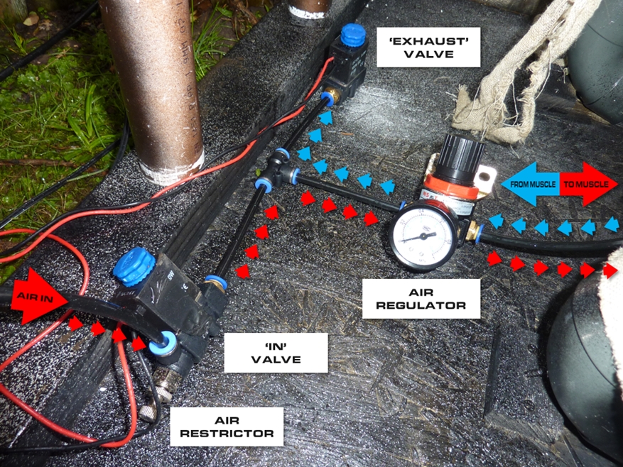
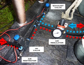
The switching of
the air supply into each muscle would be done using 12V
solenoid air valves, arranged as in the photo to the left.
Quite simply, when 12V was applied across them, they opened
and air could pass through. When they were switched off,
they shut again.
Two valves were used per air muscle. The leftmost valve in
the photo ('IN') was responsible for allowing air into the
muscle. Air came into this via the black pipe visible in the
bottom left of the photo. The other valve ('EXHAUST')
released the air from the muscle. Restrictors (the silver
rotary part on the leftmost valve) were useful to control
how fast the air could flow into the valve and up to the
muscle, which allowed me to adjust the speed of movement.
The photo also shows a regulator, which was used to limit
the air pressure going to the muscle of the figure. The
wolfman needed 3 bar to move; the other two figures used
around 2 bar. The pipe extending out
of the regulator and off the right hand side of the photo
was connected to the muscle. All the muscles, fittings and
valves were connected using 6mm nylon pipe. |
|
|
|
|
| |
|
|
|
|
|
|
|
|
|
|
|
|
|
|
|
|
|
|
|
|
|
|
|
|
|
|
|
|
|
|
|
|
|
|
| |
Due to the way
in which the valves were connected with the regulator and outlet to
the air muscle (in a T-shape arrangement, like in the
photo), it became clear that the 'EXHAUST' valve could only
be opened when the 'IN' valve was closed - otherwise I would
be draining air from the compressor and the muscle at the
same time! So the procedure to move the muscle would be
this:
1. Switch on 'IN' valve to open it. Air flows into muscle
and the muscle contracts. (Red arrows in the photo above).
2. Switch off 'IN' valve to close it once the muscle has
fully contracted. Air supply from the compressor to the
muscle is now closed.
3. Switch on 'EXHAUST' valve to open it. Air drains from the
muscle out via this valve. (Blue arrows). Muscle returns to
its normal length.
4. Switch off 'EXHAUST' valve once the muscle has been fully
drained of air.
|
|
|
|
|
|
|
|
|
|
|
|
|
|
|
|
|
|
|
|
|
|
|
|
|
|
|
|
|
|
|
|
|
|
|
|
|
|
|
|
| |
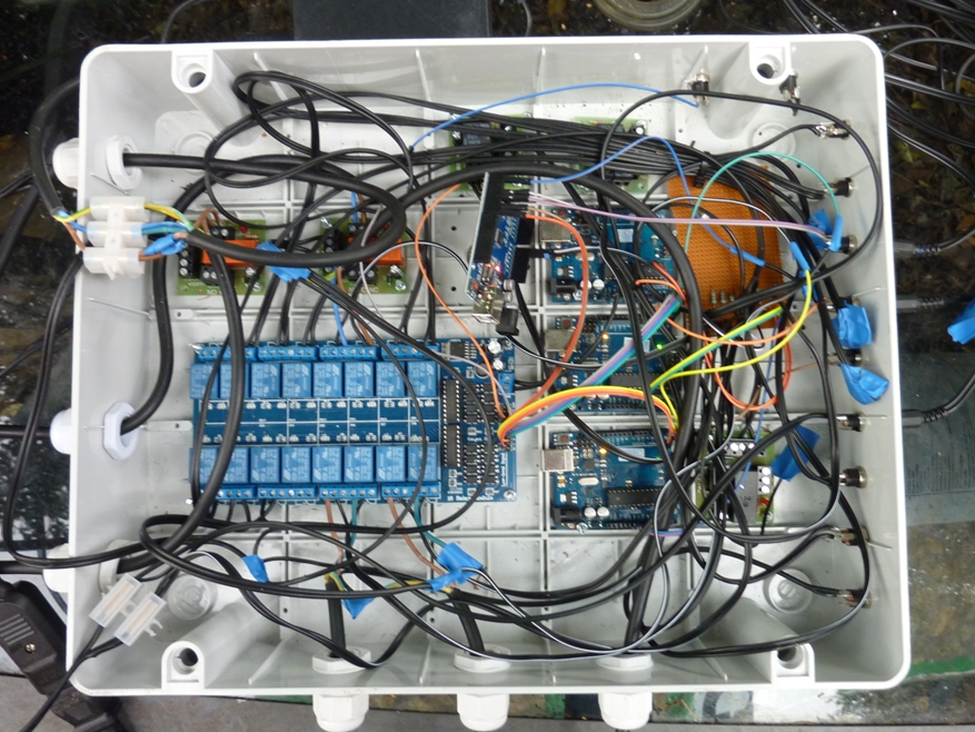
This process
would need to be electronically controlled, to manage the
switching of the valves needed to move multiple figures, as
well as receive initial triggers from motion sensors. It would be necessary for each
figure to have a pre-programmed sequence of commands that
controlled its associated air valves to specific timings, in
order to produce the movement I wanted.
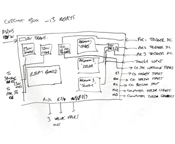
I decided to
use a series of Arduino Uno microcontrollers, connected to a
16-way 12V relay board. Each controller would be connected to its own group of relays,
switching them on and off as programmed when activated by an
external trigger.
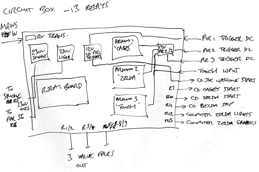
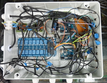
I mounted this all in a large moulded electrical box (see
photo right - excuse the cable mess, this was taken during
building!) This
system would be the 'brains' of the display. Also inside
the box were some 12V relays that were capable of switching
230V, which was useful for controlling mains lights and a
smoke machine used for a separate fire-breather effect (more
about him later!). |
|
|
|
 |
|
|
|
|
|
|
|
|
|
|
|
|
|
|
|
|
|
|
|
|
|
|
|
|
|
|
|
|
|
|
|
|
|
|
|
|
|
|
| |
 |
|
|
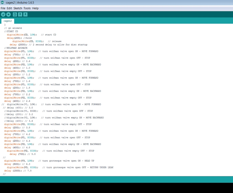
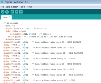
I wrote some
code for each Arduino board, which would run each time the
effects were triggered. David later came back with the
suggestion that I could have used the board's 1k of EEPROM
to record the moves of each figure 'as live'.
By connecting the controller to push switches which also ran
to each valve, I could press these to animate the figure how
I wanted whilst recording the switching into the board.
However, I'd already finished writing the code so I stuck
with that method, although puppeting the moves with each
figure in front of me would definitely have been a lot more
fun! In either case, there was also the possibility to
create more than one animation sequence for a figure, and
have the controller pick one at random upon triggering.
Each board was programmed to wait for around 10 seconds
after its animation sequence had completed. My air muscle
construction wasn't perfect, and they did leak a bit, so I
was needing more air to move the relatively heavy figure
frames - it was sensible to give the compressor a bit of
bonus time to recharge before the effects could be re-triggered. |
|
|
|
|
|
|
|
|
|
|
|
|
|
|
|
|
|
|
|
|
|
|
|
|
|
|
|
|
|
|
|
|
|
|
|
|
|
|
|
| |
I took a slight
technological step backwards for 2015, in terms of sound
effects! Whereas the previous displays were moving steadily
away from CD-based soundtracks, this year I had a big stack
of CD players at my disposal, so I decided to put the sounds
for each figure on discs, and have each Arduino board
trigger playback on the associated CD player. This
was perhaps another idea inspired from Rumpus Mansion
at Blackgang Chine, where its sounds also originate from
CD players (1993 technology, remember!) and are triggered in
a similar way by a controller for each scene.
The CD players worked well, and one of the players had a
'random' playback function, which I used for the fortune
teller figure. On the disc were around ten different
phrases; I programmed the Arduino board to start the random
function, wait for three different phrases to be played,
then stop the disc. This worked very nicely, and gave the
figure more variation. The sound effects were the basis for
the timings of the figure movements. I wanted it all to match up
and be in sync, ie. the wolfman would lunge forward and
growl at the same time! |
|
|
 |
|
|
|
| |
|
|
|
|
|
|
|
|
|
|
|
|
|
|
|
|
|
|
|
|
|
|
|
|
|
|
|
|
|
|
|
|
|
|
| |
Open-CD player surgery... |
|
|
|
|
|
|
|
|
|
|
|
|
|
|
|
|
|
|
|
|
|
|
|
|
|
|
|
|
|
|
|
|
|
|
|
|
|
| |
 |
|
|
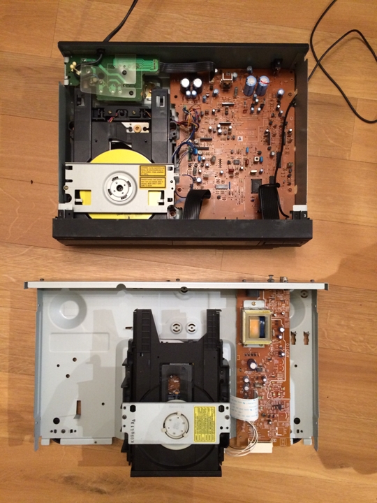
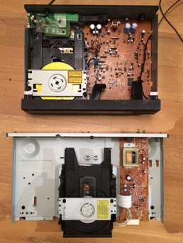
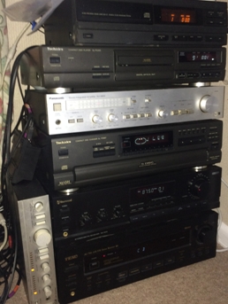
< Indulge me
on this little electronics musing...take a look inside these two
CD players I used. The top machine (JVC XL-E31) is about 25
years old, the bottom one (Technics SL-PG390) about 15.
What a difference in the circuitry required to perform the
same task!
> Here's the stack of CD players and amplifiers used for the
display. Welcome to 1990...! Each player had pieces of wire
cheekily inserted and soldered across their relevant
playback buttons for external
control by the Arduino Uno boards.
I was born in 1991, very much in the glorious era of the CD...
So when better than 24 years later to celebrate that...! I
like to think of this as my equivalent of a misty-eyed vinyl
fan digging out their old record player! |
|
|
 |
|
|
|
|
| |
|
|
|
|
|
|
|
|
|
|
|
|
|
|
|
|
|
|
|
|
|
|
|
|
|
|
|
|
|
|
|
|
|
|
| |
Constructing the figures |
|
|
|
|
|
|
|
|
|
|
|
|
|
|
|
|
|
|
|
|
|
|
|
|
|
|
|
|
|
|
|
|
|
|
|
|
| |
While I was
building all this, I was aware that I was rather keeping David in
the dark as to what my figures were looking like! I
wanted him to see them fully working, rather than as just bits
of pipe and hinges! And that's what I've done with this 2015
account...I've kept you in suspense about how they looked!
So let's have a sneak peek at how they were made...
|
|
|
|
|
|
|
|
|
|
|
|
|
|
|
|
|
|
|
|
|
|
|
|
|
|
|
|
|
|
|
|
|
|
|
|
|
|
|
|
|
| |
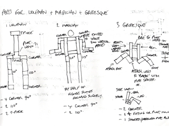 |
|
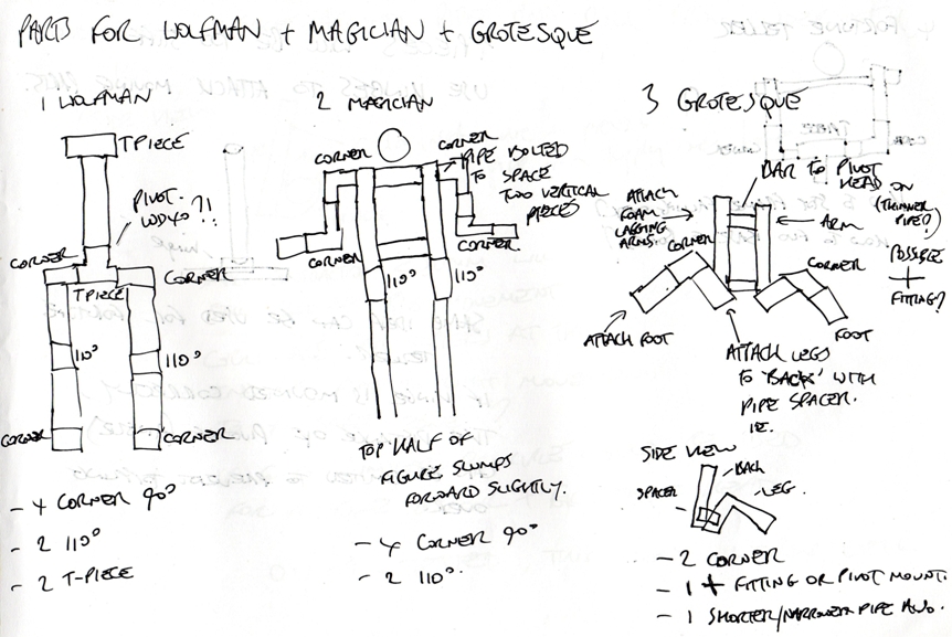
< I'd come up
with the final plan for three moving figures; the wolfman,
the grotesque (another caged monster) and the fortune
teller. The drawing to the left shows some of my early
ideas, which includes a 'magician'. He was included in the
display, but as a static figure (shown on the next page).
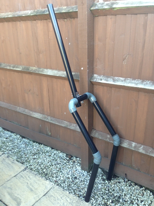
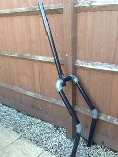
All three of my figures were built from pieces of 50mm pipe,
connected with elbow fittings. This helped to make them
lightweight, but the plastic was still surprisingly robust
and coped well with movement from the air muscle. The hinged
part (the spine of the wolfman, in the photo below, left)
was attached with bolts using standard steel hinges. The air
muscle was then fixed next to this hinge, and attached to
the moving part (eg. the spine or head).
I used foam lagging to 'bulk up' the limbs of the figures,
and also to create a 'rib cage' to shape the torsos. The
heads were polystyrene, with latex masks attached. Each
figure also had latex hands. It was great fun
finding clothes for the figures to wear; I got a few odd
looks in charity shops buying old jackets and shirts for
them...! |
|
|
|
|
|
|
|
|
|
|
|
|
|
|
|
|
|
|
|
|
|
|
|
|
|
|
|
|
|
|
|
|
|
|
|
|
|
|
|
|
|
|
|
|
|
|
|
|
|
|
|
|
|
|
|
|
|
|
| |
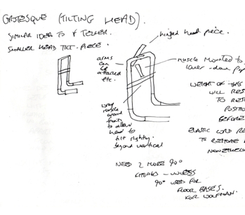
 |
|
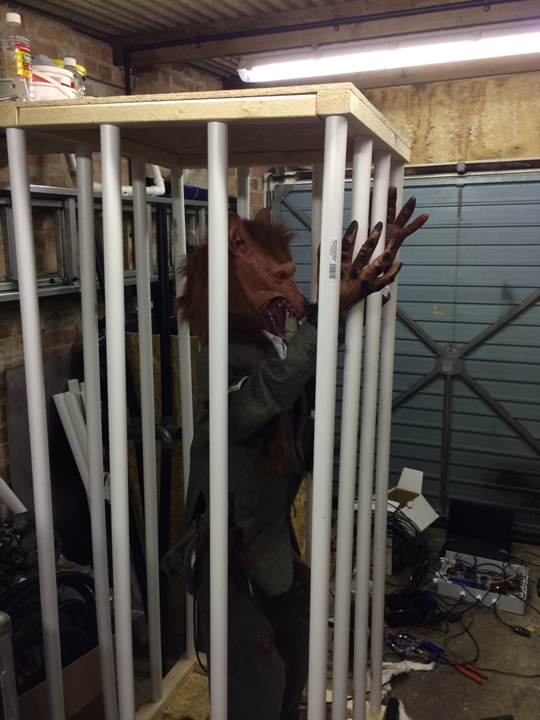
< The wolfman
frame was the most challenging to build as he was required
to be completely free-standing! His pipe legs were tightly
fitted to the floor of his cage with more elbow fittings to
prevent him from falling over!
> The grotesque and the fortune teller were easier to create
as although they were to move in a similar way to the
wolfman, they were only 'top halves' with no legs!
The fortune teller's lower half would be hidden behind her
table, and the majority of the grotesque's body would be
disguised under rags! |
|
 |
|
|
|
|
|
| |
|
|
|
|
|
|
|
|
|
|
|
|
|
|
|
|
|
|
|
|
|
|
|
|
|
|
|
|
|
|
|
|
|
|
| |
 |
|
|
|
The end of
October was approaching, and I was putting the finishing
touches to programming the figures. The wolfman hadn't been moving as
well as I'd hoped. His hands were fixed to the bars of his
cage, and it turned out that as a result he couldn't move
forward as much - his arms were preventing it somewhat.
The solution was to cut his foam arms away from his body, so
that only his jacket was connecting them to his torso! This
gave him a lot more freedom of movement, and suddenly he was
rocking and rattling his cage a treat!
Zelda was easier to build and operate - no heavy jacket or
arms, just purple fabric, hands, and a lightweight
polystyrene head with mask, so she required less air
pressure to move. |
|
|
 |
|
|
|
|
|
|
|
|
|
|
|
|
|
|
|
|
|
|
|
|
|
|
|
|
|
|
|
|
|
|
|
|
|
|
|
|
|
|
|
|
|
|
|
|
|
|
|
|
|
|
|
|
|
|
|
|
|
|
|
|
|
|
|
| |
 |
See the
wolfman moving before he was modified - his
movements were restricted by his hands and arms
(.mp4, 4.5mb) |
|
|
See Zelda working
in this early test clip of the figure
(.mp4, 4.6mb) |
|
|
|
|
|
| |
|
|
|
|
|
|
|
|
|
|
|
|
|
|
|
|
|
|
|
|
|
|
|
|
|
|
|
|
|
|
|
|
|
|
| |
I decided to
call the display 'The Carnival of Horrors'. As well as the
moving figures, I had some other special effects and tricks
up my sleeve to spook our visitors! It was finally time for
the carnival to open... (and for you to finally see the
figures in action!)... |
|
|
|
|
|
|
|
|
|
|
|
|
|
|
|
|
|
|
|
|
|
|
|
|
|
|
|
|
|
|
|
|
|
|
|
|
|
|
|
|
| |
 |
|
|
|
|
|
|
|
|
|
|
|
|
|
|
|
|
|
|
|
|
|
|
|
|
|
|
 |
|
|
|
|
|
|
|
|
|
|
|
|
|
|
|
|
|
|
|
|
|
|
|
|
|
|
|
|
|
|
|
|
|
|
|
|
|
|
|
|
|